
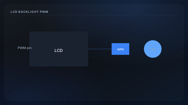
The parallel LCD interface uses RS, E, and D4–D7 for text—documented in LCD GPIO map. The LED backlight is a power circuit, often switched through a transistor because Arduino pins cannot supply backlight current directly. PWM or timed dimming keeps the garage readable at night without a always-on glow heating the enclosure.
Wiring patterns
- Direct digital pin — on/off only; simplest for bench tests.
- PWM pin — smooth dimming via
analogWriteon supported pins. - Timer-based off — firmware turns backlight off after idle minutes.
Firmware interaction
Backlight changes do not require re-init of LiquidCrystal. Coordinate with display format refresh so dimming does not coincide with unreadable contrast—Vo pot still sets character visibility via power rails.
Power budget
Overnight off saves modest current but reduces heat in sealed enclosures. Ensure SPI pins stay free if choosing PWM on timer-overlap pins—verify pinout chart for your board.